Extended Reach Equipment
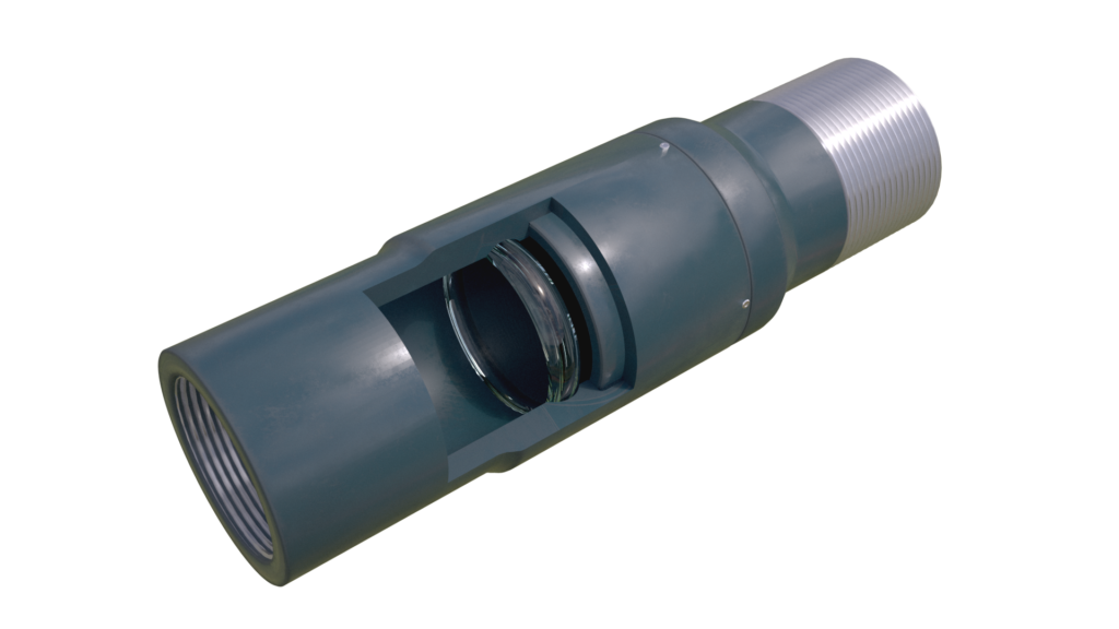
Running casing to depth is challenging in long lateral sections because of the excessive drag forces. To improve casing running capabilities, the CleanBore™ Buoyancy Sub is placed in the heel to trap an atmospheric chamber in the horizontal section of the casing, significantly reducing drag force. Hook load is concentrated in the vertical section, allowing the operator to land strings in ultra-long laterals. With the casing on the bottom, applied pressure activates the CleanBore™ Buoyancy Sub and leaves a fullbore ID for cementing and completion operations.
The CleanBore™ Buoyancy Sub product line utilizes proprietary glass machining and tempering specifications. The result is a high-strength glass that can withstand shocks during handling and well operations, while ensuring complete disintegration upon activation to leave a fullbore tubing ID.
CleanBore™ Buoyancy Sub Advantages
- High Pressure: Strongest single-layer glass, rated over 15,000 psi
- High Torque: Designed to the torque ratings of all commonly used casing connections.
- Precise Activation: Aerospace technology to provide activation pressure accuracy of +/- 5%
- Casing & Liner Compatibility: Designed with the largest running clearances allowing a combination of casing strings to be run. Compatible with all cement wiper plug configurations.
- Single Glass Disk: Less volume of glass to pump through float equipment.
- No Debris: Shatter Glass technology completely disintegrates and eliminates need for debris trap
- Truly Fullbore: Smooth bore after activation and drift larger than the casing.
- Perfect Track Record: 1200+ runs with 100% success.

CleanBore™ Buoyancy Sub, High-Strength Proprietary Glass
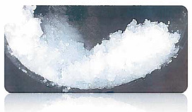
The high-strength proprietary glass shatters into tiny, sand-like fragments can be pumped through float equipment without any risk of plugging.

CleanBore™ Buoyancy Sub Specifications
| Size and ppf | Mat. Yield* [ksi] | Max Sheer dP** [kpsi] | ID [in] | OD [in] | Burst*** [kpsi] | Collapse*** [kpsi] | Temp** [°F] | Body Yield*** [klb] | Torque [ft-lb] |
| 2-3/8 4.7# | 80 | 10 | 2.00 | 3.20 | 18.2 | 14.8 | 300 | 148 | 2694 |
| 2-7/8” 6.4# | 80 | 10 | 2.44 | 3.65 | 15.6 | 13.1 | 300 | 188 | 4373 |
| 3-1/2" 9.2-12.7# | 125 | 10 | 2.99 | 4.50 | 23.6 | 19.8 | 300 | 470 | 14800 |
| 4-1/2" 13.5# | 125 | 10 | 3.92 | 5.40 | 18.6 | 18.5 | 300 | 561 | 21700 |
| 5" 18-21.4# | 125 | 10 | 4.28 | 6.00 | 19.7 | 18.8 | 350 | 761 | 34200 |
| 5-1/2" 17-23# | 125 | 8.5 | 4.89 | 6.50 | 16.9 | 15.9 | 300 | 779 | 40000 |
| 5-1/2" 20-23# | 125 | 10 | 4.78 | 6.50 | 19.0 | 18.1 | 300 | 872 | 40000 |
| 6" 24.5# | 125 | 7.5 | 5.20 | 7.15 | 18.8 | 17.6 | 300 | 1049 | 51900 |
| 6" 24.5# | 125 | 10 | 5.20 | 7.40 | 16.9 | 21.9 | 300 | 1040 | 54500 |
| 7” 32# | 80 | 7.5 | 6.09 | 8.33 | 10 | 8.9 | 300 | 746 | 52170 |
| *Material specification is configurable. **Tools validated with physical testing to listed differential pressure and temperature. ***Calculated ratings based on Lamé’s formula and include no safety factor, rounded down to nearest 100 psi. Actual tool ratings may be higher than listed, depending on actual housing material yield strength. System limitation will depend on connections and tube yield strength. |
The patented Davis Flotation Collar is designed for use in running casing in substantially horizontal wellbores. Incorporated into the casing string, the device serves as a temporary barrier inside the casing. In so doing, it allows the portion of the string below it to be filled with air (no fluid) and the portion above it to be filled with drilling fluid.
Floating the bottom portion of then casing reduces the drag against the wellbore, while filling the upper portion with drilling fluid adds weight to the casing string to push it into the hole. This feature facilitates running casing in highly deviated wells and, in many cases, permits successful casing runs that would otherwise be extremely difficult if not impossible.
Once the opening sleeve is activated by casing pressure, allowing the drilling fluid to displace the air in the lower section of the casing string, normal cementing operations can begin immediately. Additional pressure on the bottom cementing plug releases the DFC assembly so that it can be pumped down to the float collar. The top cementing plug displaces the cement and lands and seals on the bottom cementing plug/DFC assembly.
Unlike earlier devices that must be set inside the casing and then retrieved after landing the casing (requiring one round trip of the drill pipe and spacing the top of the last casing joint at the rotary table), the Davis Flotation Collar is installed in the same manner as a float collar.
Applying pressure to the inside of the casing string is all that is required to release the trapped air at the bottom of the casing string. This pressure is adjustable at time of manufacture to accommodate different pressure requirements.
The Davis Flotation Collar is self-contained and requires no other running, setting or retrieving tools. The inner sleeves of the device provide a good seal for the cementing plug against the float collar, and they are easily drilled out with either PDC or conventional rock bits when drilling the float equipment.

