Wireline cables are most susceptible to damage during their first few runs into and out of a wellbore when the cable is essentially “new.” Although this seems contrary to what you would expect, the exposure to the wellbore environment helps “season” a new cable and prepares it for life into and out of a wellbore. These first several runs are critical to ensuring you get the maximum trouble-free operation from your cable.
As delivered by the manufacturer, a new cable undergoes essential changes when it is put into service initially. These changes are tension, temperature, and rotation.
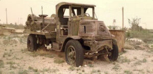
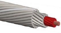
Cable tensions and wellbore temperature during field operations are much higher than during manufacture. These repeated higher tensions at elevated temperatures produce an embedment of the inner armor into the conductor insulation and a reduction of the diameter of a new cable in the range of 0.005 inches. Quality Cables uses a series of pressure rollers to partially embed the inner armor into the plastic core before applying the outer armor during manufacturing. This process reduces the diameter changes typical of a new cable, which starts the seasoning process before running in a well. In the picture below, the insulation depicted in red shows the indentation made during the manufacturing of Quality’s cables.
All cables used in oilfield service have an armor design that develops a torque proportional to the load on the cable. The torque of the outer armor wires is always greater than the opposing torque of the inner armor wires because there are generally more armor wires on the outer, and the distance from the center is greater (increasing leverage). Under load, the outer armor dominating will attempt to rotate and unwind the cable until there is a torque balance between the armor layers.
A cable is subject to only a few hundred pounds of tension during manufacturing, so there is essentially no torque in a new cable as delivered. When installed on a truck, the spooling tensions are significantly higher than during manufacturing, and because the cable is not free to rotate, the cable will develop significant torque. When making the first field operations, this new cable will try to rotate to equalize this built-up torque and support the weight of the tool string. To illustrate the magnitude of this problem, consider a new 5/16-inch cable deployed in a straight 20,000-foot well. The total rotations a new cable end would need to rotate to equalize the torque could be over 400.
Quality Cables decreases the problems associated with cable rotation by including a special blocking material that increases the friction between the inner and outer armor, reducing cable rotation. The armor slowly loses this initial blocking material after repeated operations. With standard cables using galvanized steel armor wires, these spaces between armor wires now become filled with zinc and iron corrosion by-products. When combined with the roughening of the wire from corrosion, these by-products increase the friction between the inner and outer armor, thereby reducing cable rotation.
Cables built for operations in H2S and extreme corrosive well conditions use special alloy armor wires. Alloy wires do not pit or generate corrosion by-products. Without this friction from corrosion, alloy cables rotate freely throughout their life after the initial blocking material is lost.
Operations using alloy cables are frequently in wells containing toxic well gases, where hydraulic pack-offs are generally kept much tighter than in regular operations. These conditions result in additional cable unwinding and loosening of the outer armor. Alloy cables must have the armor tightened and set with post forming throughout their life. There are no standard rules for servicing alloy cables, but bringing a new alloy cable to a service center after the first job and afterward, from every 10 to 20 runs, is good practice.
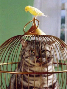 All cables that become loose, particularly new cables, are more susceptible to damage, including: 1) drum crush, 2) outer armor wires being “milked” into a “bird cage,” and 3) a reduced breaking strength.
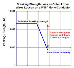
Notably, the breaking strength of a normalized cable comes from all of the inner and outer armor wires combined. When a cable becomes loose, the load shifts from all the wires to only the internal wires, dramatically reducing the breaking strength, as shown in the graph below.
Tips to Help Prevent Damage to New Cables and Increase Cable Life
- To allow a new cable to rotate and become “normalized,” it is important to choose the first operations carefully. Select operations with minimum mechanical drag downhole, where little or no pack-off pressure is required and where the hole is relatively straight. In practice, boreholes are never straight, and the end of the cable is never entirely free to rotate, so it takes a new cable several trips in the hole to spin out and become totally “normalized.” Follow the same rules any time a new part of the cable comes off the drum for the first several times.
- When coming out of the hole, cable tension increases due to friction and the weight of the tool string. This higher tension will cause the cable to rotate and the outer armor to unwind. Line speed is critical; the faster you run in the hole, the less tension the cable experiences. Coming out of the hole at high speeds creates increased tension and captures the cable loosely. Tension reduces when going back into the hole, and the cable rotates to tighten the outer armor. A good operating rule to allow a cable to wind and unwind is typically:
- While going in the hole, do not allow the tension at any depth to fall below 2/3 of the static tension at that depth.
- Come out at a speed not greater than the speed that increases the tension by more than 1 1/3 of static tension at that depth.
- When special operating conditions do not allow for normal cable speeds or tight pack-offs are needed, the cable will unwind and develop loose outer armor. Correcting this condition will require the cable to be taken to a cable service shop to have the armor tightened and post-formed; otherwise, you could jeopardize the cable’s ultimate breaking strength.
- For new cables, when running in, stop every 1000 to 2000 feet (or whenever the customer permits) to allow the cable to regain tension and properly spin out. At this point, pull back 50 to 100 feet before running further into the well.
- Avoid deviated wells if possible until the cable is seasoned.
- Avoid pressure with a hydraulic pack-off and ensure the flow tubes are a minimum of 0.004 inch to 0.006 inch clearance.