As a part of regular maintenance, cased hole wireline cables need to be “cut back” to remove portions of the cable that either have excess diameter reduction or where the armor wires have become brittle. Although diameter reduction and loss of ductility (embrittlement) often coincide, they are independent. Diameter reduction is the result of mechanical friction or plastic embedment. At the same time, loss of ductility results from a chemical attack resulting in an alteration of the microscopic structure of the steel.
Electromechanical wireline cables are subjected to tension and wear whenever they enter a well bore. Vertical wells are the best-case scenario for minimum wear and drag, but even the most ideal vertical wells have deviations. The cable will rub against the sheaves, measuring head, casing, and flow tubes, causing friction between the two metals and reducing the cable diameter.
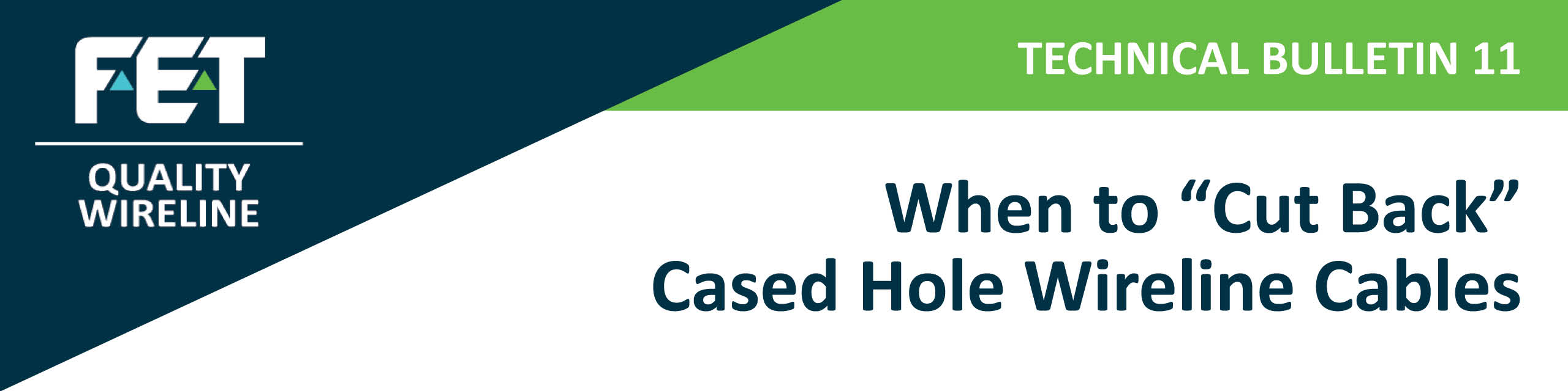
With the advent of horizontal wells and pump-down applications, cable wear and tensions have increased significantly. As a cable wears, its diameter decreases due to the outer armor wires flattening and getting smaller, as shown in the pictures below.
This loss in outer armor wire diameter results in
1) reduction of the overall breaking strength of the cable,
2) the weak point at the cable head becoming unknown due to both the reduction in wire strength and the potential for slipping inside cone-style cable heads and
3) a poor grease seal and difficulty sizing flow tubes during pressure work.
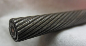
Diameter loss can also occur when you subject a cable to very high tension, which happens more today than in years gone by due to the complex well geometries and depths. At very high tensions, the wires will embed into the plastic, creating a smaller overall cable diameter, as shown in the picture below. Although this does not reduce cable strength, it can create issues related to adequately sizing flow tubes and potentially contribute to prematurely electrically shorting the cable.
Diameter loss can also occur when you subject a cable to very high tension, which happens more today than in years gone by due to the complex well geometries and depths. At very high tensions, the wires will embed into the plastic, creating a smaller overall cable diameter, as shown in the picture below. Although this does not reduce cable strength, it can create issues related to adequately sizing flow tubes and potentially contribute to prematurely electrically shorting the cable.
Over time, a cable will become tapered where the diameter at the tool end is smaller than the diameter farther up the cable, which can result in difficulty getting a proper grease seal through the flow tubes. It is important to understand the diameter over the entire working length of the cable to ensure that problems related to sizing flow tubes do not occur. We highly recommend that cable diameters along the cable length be measured frequently and recorded in the cable record book by a qualified distributor.
Cased hole wireline companies generally work in several fields for oil and gas companies. Every oil and gas company has specific operational practices for drilling, completing, and stimulating production. These practices involve many different chemicals, including some that hurt the life of a wireline cable. In addition to the manufactured chemicals in the wellbore, naturally occurring chemicals and gases negatively affect GIPS wireline, including hydrogen sulfide, carbon dioxide, and chlorides. Because wireline companies operate in many different wells, and knowledge of well conditions is only sometimes well known, the potential for corrosion or embrittlement can be high.
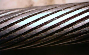
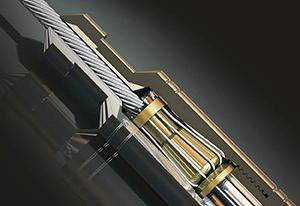
Today’s operational environments demand that everyday work practices include regular inspections for diameter loss and loss of ductility. You should perform inspections whenever re-heading unless operating in a well-known environment. As shown in the picture below, the wires are bent around the cone during re-heading, creating a stress concentration. These stress concentrations are susceptible to corrosion and cracking. After re-heading, grease must be applied inside the cable head covering these bent wires.
Routine wireline inspections should include the following:
» Visual examination of the whip end for any mechanical damage.
» Measurement of the outer armor wires for wear and ovality.
» A test for ductility.
If operating in an area known to have the potential for any chemical attack, perform re-heading and the wrap test more frequently. These tests only take a few minutes and could prevent a significant cable problem. Follow the procedures for measuring wear and ductility outlined below.
Testing for Wear:
1) Cut back 50 feet of cable from the whip end.
2) Inspect a two-foot sample for mechanical damage or unusual properties.
3) Remove the outer armor wires.
4) Clean the outer armor wires.
5) Using a set of dial calipers (micrometer or vernier calipers), measure the diameter of the individual wires at the narrowest point (flat spot) and the widest point. We recommend a minimum of six wires.
6) If the wire has lost 12%-15% of its original diameter, cut back the cable further.
7) Cut back 100-150 feet and re-inspect by following steps 2 through 6.
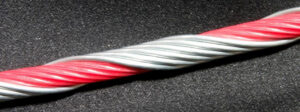
Testing for Ductility:
Once the cable is verified to have an acceptable amount of metal left on the outer armors, perform the ductility test as follows:
1) Cut approximately one foot from the wire sample.
2) Bend about 3 inches of the wire 90 degrees and place the short end in a vice.
3) Wrap the long end around the diameter of the short end tightly, making slow turns.
4) After making five complete wraps, slowly unwrap the wire.
5) Inspect for any breaks or cracks.
6) If the wire breaks or cracks, cut back and re-test by repeating steps 2 through 5.
We address these issues and field equipment to use for testing and recording test data electronically in our cable schools. Please call your local Quality Wireline sales representative to learn more.