A historical review and tips on the installation of wireline cable and what to look for to prevent drum crush and other field-related problems:
In the early 1950s, the first double-armored cables had rubber-insulated conductors installed directly from the factory shipping reel to the truck drum. It was common practice to wedge a 2×4 under the flange of the shipping reel to establish some extra tension. Major service companies developed a “dead man” setup where the turn-around sheave was attached to a 500-pound weight. You had to adjust the brakes of the payoff continuously to keep the weight off the ground. Later, it increased to 1000 pounds.
When logging the first “very” deep wells (18,000-20,000 feet) in West Texas, several electrical failures in US Steel cables were labeled factory defects. They discovered that all the failures had occurred at a point in the cable that had not been off the drum. In fact, the shorts were several layers down from any point on the cable that had been in the hole. It was the birth of what is now called “drum crush.” A test solution was to initially spool a new cable back and forth between two trucks, building up the spooling tension 500 pounds at a time until establishing a tension equal to the tension in the field. This test worked and unveiled the first understanding of “drum crush.”

In the late 1950s, with a better understanding of “drum crush,” workers employed different solutions to reduce spooling tension at the well site, which included using a powered capstan or sheave wheel. Later, truck drums improved to take the higher tensions, and capstans were installed in the major spooling shops to install cable at the required higher spooling tensions.
The single-break system was the standard for spooling a cable on a drum years ago. With this method, the cable made the first wrap tight against the flange. As this first wrap was complete, the cable had to bend severely to step over a full cable diameter for the next wrap. This single-break pattern became the standard for many years, and some still use it as it is easier to install. This tight bend can lead to electrical failures when encountering high spooling tensions. Today’s preferred spooling pattern is the double-break pattern, where the cable moves over half a cable diameter each half revolution of the drum. This pattern requires a less severe bend in the cable to move over just half the cable diameter at a time.
You can establish a double-break pattern when the cable makes the first half wrap against the flange, and then a filler of half cable diameter is placed against the drum flange to move the cable over for the last half wrap. It also requires a filler for the last half revolution of the final wrap on the drum. For the entire cable to spool properly, the breaks must form a straight line across the drum, and the cable must move from the bed layer to the second layer at a point precisely opposite the entry point of the cable on the starting flange.
When placing a covering layer back over a lower layer, the covering layer wraps fall in the grooves between the lower layer wraps. The diameter of the spooled cable fitting in the grooves increases the spooled diameter by only 0.87 of a cable diameter. Theoretically, the spooled diameter increases by a full cable diameter at the crossover point. In practice, the cable gets “smashed” at the crossover, so the diameter is not a full cable diameter.
On the second and subsequent layers, the breaks fall on top of the breaks of the underlying layer, causing a diameter build-up. If this diameter build-up is just at one point, as with the single break, the drum full of cable is dynamically out of balance. A drum spooled with a single break in deep hole operations will severely shake the truck at high line speeds. Double-break spooling avoids this problem.
Tips to Help Prevent Drum Crush:
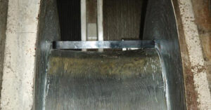
- Place a straight edge across the drum core, as shown in the picture below. There should be no visible gaps, indicating dips in core diameter. These dips may cause the cable to drop into the valley and lead to gaps in the spool job, causing changes in tension and, ultimately, field problems that may cause drum crush.
- Measure and record the distance between drum flanges at the core and the top of the flanges. These distances should be at most 1/10 of the cable diameter. After installing the cable, if this distance has increased by more than half a cable diameter, it would indicate that spooling problems may occur in the field. The extra space between the flanges creates gaps in the cable. The cable may squeeze into these gaps under load, leading to drum crush.
- Check the condition and location of the cable entrance hole on the drum flange. This hole must be touching the drum core. The hole should allow a smooth cable entrance of the cable onto the drum to start the first wrap properly. A kink may result if the cable is not correctly laying next to the flange as the second layer covers it. The cable could short out at this location when adding more and more layers under higher and higher tensions.
- Establish the double break pattern.
- When establishing bed layers during cable installation, it is important to ensure that you do not stop while spooling the high-tension layers because the cable tension will fall off, resulting in a “soft” section in the cable that could lead to drum crush. If a stop occurs, it is good practice to return to the bed layers and start over.
- When running into the well, it is vital to prevent the loss of tension on the cable because the breaking point backs up, the spool job loosens, and the cable becomes “soft.” A cable under tension or “hard” can withstand much higher axial loading. If you pull tension across this “soft” section, the cable can crush itself, which may not occur immediately but could happen several jobs later. Once tension is lost, the maximum tension that can be applied safely is twice the measured tension when the tension was lost. To prevent damage, you must take the cable to a service center to re-establish the proper tension profile.
- Periodically, have the cables tightened at a qualified service center to ensure that the cables remain normalized (i.e., the outer and inner armors are torque balanced).