
The wireline sheave is an integral part of wireline operations and much more critical in extending the life of a wireline than many people know. Using an inappropriately sized sheave for a wireline all too often damages the wireline, usually occurring after just one run in the well! Typical types of damage include stresses putting the wireline out of round, loose outer armor, broken strands, and ultimately reduced breaking strength of the wireline. You can easily avoid these problems with some basic and essential education on marrying the correct sheave with each wireline.
We realize there are many reasons why some people select one manufacturer or style of sheaves over the other; however, from a wireline manufacturer’s perspective, two characteristics of a sheave matter most: 1) groove design and 2) diameter. Let’s look at what can happen with a wireline due to each sheave characteristic.
Sheave Groove Design: What Can Go Wrong
Figures 1 and 2 illustrate a wireline using a sheave with a groove diameter that is too small. As you can see in the relaxed state of Figure 1, the wireline rides on the edges of the sheave because it is not appropriately cradled.
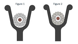
When applying tension in Figure 2, the wireline pulls down into the groove and deforms to the shape of the groove. This permanent deformation can result in an “out of round” wireline where several issues can occur, including:
- Problems getting through flow tubes on pressure work,
- Problems when trying to spool the cable back onto the drum correctly and
- Excessive wear on both the cable and the sheave.
Figures 3 and 4 depict a sheave with a groove diameter too large for the wireline. Figure 3 shows a wireline in a relaxed state resting at the bottom of the sheave groove without touching the sides for support.
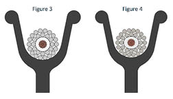
When applying tension in Figure 4, the wireline flattens into the groove and can permanently deform, causing:
- Problems getting through flow tubes,
- Spooling trouble, and
- Prematurely wearing a track in the sheave.
Sheave Diameter: What Can Go Wrong
If you have ever bent a wire back and forth until it breaks, you have experienced “yielding” and “work hardening” of steel. When you bend a wire at too sharp of a radius, the stresses on the edge of the wire increase beyond the yield strength of the material; in other words, you have permanently deformed the wire. Each time you “yield” the wire this way, it becomes slightly longer. As you continue to do this through several cycles, the metal “work hardens” and becomes increasingly brittle until the stress on the wire exceeds the ultimate tensile strength, and it snaps. The same is valid with wireline.
The smaller the sheave, the higher the stress applied to the wireline. If the wireline travels around a sheave, creating too tight of a bend, the armor on the outside of the bend gets stretched. As the wireline straightens, these outer wires are more extended, resulting in loose armor. Loose armor can accumulate below the flow tubes, resulting in a bird cage and the need to kill the well to remove the wireline. If allowed to continue, the wires “work harden” and eventually fail.
Catalysts that contribute to work hardening include:
- Number of cycles
- Type of alloy (how hard it is to begin with)
- Presence of chemicals (many cause the wire to be more brittle)
- Diameter of the outer armor wires (plays a crucial role in total stress)
- Sheave diameter
- Load on the wireline combined with the bending stress
Selecting the Right Wireline Sheave
In most operations, the sheave groove size and shape are far more critical than the sheave diameter. However, the proper sheave diameter must be used in applications where the wireline will have high tensile loads. Diameter and groove design are essential parameters on every sheave but even more critical on the top sheave, where the wireline travels around the sheave 180 degrees. In contrast, generally, on the bottom sheave, you are at a 90-degree angle with less contact with the wireline on the sheave.
Groove Diameter: Figure 5 shows an appropriately sized sheave for the wireline. Cradling the wireline supports the side loads, and the shape of the wireline will remain constant under tension.
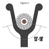
Note:
» Proper grove diameter: 1.0 to 1.04 wireline diameter
» Proper grove shape: 135 to 150 degrees of support as depicted in Figure 5.
Sheave Diameter: Typical industry guidelines are:
» Depth <25,000 feet (8,000m), minimum sheave diameter is 400 times the outer armor wire diameter (not the wireline)
» Depths >25,000 feet or high loads, the minimum sheave diameter is 600 times the outer armor wire diameter
Example:
5/16-inch cable – outer armor wire is 0.0445 inch
The minimum sheave diameter for normal operations less than 25,000 ft. equals 0.0445 inches * 400 = 17.8 inches (18-inch sheave)
Following these simple guidelines will extend the life of the wireline and the sheave. A few last pointers include:
» Do not use the same sheave for multiple diameters of wireline.
» The bigger the diameter sheave, the less stress is applied to the wireline, and it will help to extend the cycles or runs that this wireline can perform.
» Ensure proper alignment of sheave and truck to prevent loosening of the armor.