This technical bulletin aims to provide a basic understanding of electrical leaks and a procedure for field personnel to identify the type and location of an electrical leak and, if possible, keep the wireline unit working.
Although locating electrical leaks can be complicated, a skilled operator can resolve most problems in the field using a good quality ohmmeter that reads to 1/10 Ohm, saving a trip to the service center and allowing the wireline unit and crew to finish the job.
Typical steps to identify electrical leaks are:
1) Tool String – Testing the tool string is the simplest and easiest repair in the field, as you can usually find spare tools on the wireline unit. If the spare tool works, this was likely the problem.
2) Cable Head – If the tool string checks out well, the next step is to check for problems in the cable head, where most electrical leak-related issues occur and are typically due to human error. To check the cable head, cut the cable just above the cable head and test the electrical integrity of the head. If you locate the fault, rebuild the cable head and reattach the tool.
3) Collector (Slip) Rings – Many electrical problems occur in the collector rings, the coaxial cable going from the collector rings to the control panel, and occasionally the control panel. Loose wires, corrosion, wear, pressure washing or steaming the unit, and faulty equipment contribute to these problems.
a. If the leak still exists after testing the cable head, disconnect the collector ring from the cable and test the electrical integrity of the ring through to the panel.
b. If there is a problem, disconnect the coaxial cable from the collector rings and test the collector ring independently.
c. If the collector ring is good, disconnect the coaxial cable’s other side from the control panel and test the coaxial cable. Test the control panel next if the problem is not in the coaxial cable.
4) Wireline – If the electrical problem was not in the collector ring to the control panel, test the wireline before progressing to the coaxial cable and control panel. The most common areas where wireline problems occur are:
a. Working Part of the Cable – Physical damage during rigging up, not using a gooseneck, perforating kickback, jumping sheaves, excessive temperature, excessive tension, offset conductor, or broken inner armor contribute to failures in this part of the cable.
b. Drum End of the Cable – Drum crush, installation problems, and failure at the drum entry hole are common causes of failure.
Understanding the typical causes of leaks and shorts will speed up the investigation process. Leaks can occur in many forms, each with unique challenges in locating the leak. The common leak types, which can happen in the tool string, cable head, collector rings, or wireline, include:
- Dead Short – The conductor is in direct contact with the armor; this is the simplest type of short to locate.
- Intermittent – This is the most challenging type of leak because it is not always apparent.
- High Resistance – Leaks where the leak resistance is much greater than the conductor resistance can be challenging to locate.
- Wet Leaks – Occur when there is moisture in the leak. Saltwater complicates wireline leaks because it causes a small voltage between the copper conductor and the zinc coating on the armor wire. This potential will create misleading resistance readings, and accurate leak location in the field is impossible.
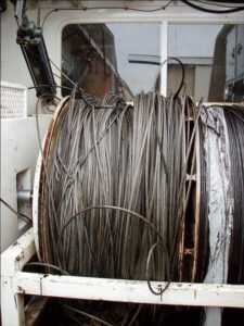
- Multiple Leaks – Occur when a wireline has several leaks. The cable located to the right likely has more than one electrical leak.
If the problem lies within the wireline, determining where the leak is relative to the tool determines the possibility of making repairs in the field. Although there are several ways to identify electrical leaks in the wireline, only one method can be used effectively in the field. Regardless of the measurement technique, cable length must be known, recorded accurately, and maintained in cable record books.
It is imperative to maintain accurate cable record books.

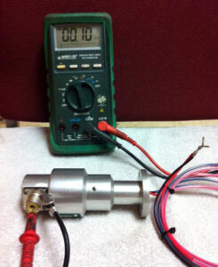
The dead short leak is the only type you can effectively deal with in the field. A good quality ohmmeter (Fluke) that reads to a minimum of 0.1 Ohms is essential in determining if you have a dead short leak. Use the following methodology to test for a dead short:
1) The first step is to short your meter leads and record this resistance reading. Subtract this lead resistance from all resistance measurements to eliminate errors due to the resistance of the leads.
2) Disconnect both cable ends and ensure the leads are clean.
3) Measure the resistance of the conductor to ground (armor) on the whip end Rw.
4) Reverse the leads and again measure Rw. If the resistance significantly differs with the leads switched, you have a wet leak and a precise location in the field is impossible. Proceed to step 7. If the readings are the same, proceed to step 5.
5) Measure the resistance of the conductor to ground (armor) on the drum end Rd.
6) If the leak is not wet, use the formula below to determine if you have a dead short, where Rc is the resistance of the current length of the conductor (from the cable record book).
If the value of Rc in the cable record book is questionable, measure the conductor resistance.
If (Rd + Rw – Rc) < 300 Ω, you have a dead short; otherwise, you have a high resistance leak. If you have a dead short, skip step 7.
7) If there is a high resistance or wet leak, the next step before going to a service center is to unwind several hundred feet of cable and, with the Ohm meter attached at the drum end, watch the Ohm meter as this loose cable flexes along the length by hand. It is a crude but sometimes very effective way of leak location as many cable leaks occur within a few hundred feet of the whip end. After finding the leak, cut the cable and test. If the leak is still present, you must take the cable to a service center.
If the resistance is less than 300 Ω, follow these steps to determine the leak’s location.
1) Find the cable’s total length (L) from the cable record book.
2) Calculate the cable length to the leak from the whip end (Lw) using the following formula:
Lw = (Rc + Rw – Rd) x (L / (2 x Rc))
3) Calculate the cable length to the leak from the drum end (Ld) using the following formula:
Ld = (Rc + Rd – Rw) x (L / (2 x Rc))
This example shows how to use the formulae:
L = 24,500 ft. (7,468 m)
(For metric, use meters in the same formulae)
Rc = 68.6 Ω
Rw = 149.4 Ω
Rd = 205.2 Ω
First, test to see if it is considered a dead short:
(Rd + Rw – Rc) = 286.0 Ω Less than 300 Ω
Check leak distance from the whip end:
Lw = (68.6 + 149.4 – 205.2) x (24,500 / (2 x 68.6)) = 2,286 ft.
Check leak distance from the drum end:
Ld = (68.6 + 205.2 – 149.4) x (24,500 / (2 x 68.6)) = 22,214 ft.
Once you have located the leak, slack the cable, examine it for physical damage, and manually flex it while observing the leakage resistance. You should find variations in the ohmmeter reading if you are at the leak. If the leak is close enough to the whip end that you can spool down and cut off, and you have enough cable remaining to perform the current services, then do so. After cutting out the short, test the remaining cable to ensure electrical integrity. Re-head and finish the job.
If the leak is too far from the whip end to cut out, you must take the cable to a service center for inspection. At a service center, they are well-equipped to deal with all types of leaks. Burning a leak out with a “burn-out” box is the fastest way to identify difficult leaks. The service center will also have more sophisticated equipment than an ohm meter to try and locate the exact point of failure. If the service center suspects the damaged cable is from mechanical damage or temperature, a burn-out box will save time finding the leak. However, if it is essential to determine the cause of the leak, then do not use a burn-out box as it will destroy the area around the leak and likely make it impossible to perform a root cause analysis of the failure.
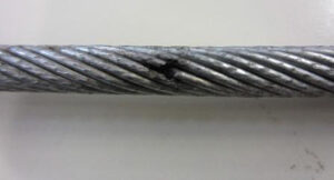
Note: This picture shows the damage to the conductor and the armor as a result of using a burn-out box.