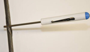
Wireline cables are susceptible to excessive torque accumulation during operations where the torque cannot dissipate. A few contributing factors to excessive torque accumulation include wellbores with a deviated vertical section, orienting weight bars, and excessive running speeds. When deploying an Enviro-Lite coated cable, it is necessary to use a wireline swivel adapter as a countermeasure against these contributing factors. Below are the recommended run frequencies of a swivel adapter when deployed with an Enviro-Lite coated wireline cable.
You should deploy a wireline swivel adapter:
Consecutively, for the first 50 runs on a new Enviro-Lite cable.
For five (5) consecutive runs every 50 runs during normal operations where not using oriented weight bars, the minimum recommended tensions are achievable, and the lateral section does not exceed 15,000 ft.
For five (5) consecutive runs every 20 runs while using orienting weight bars.
For five (5) consecutive runs every 20 runs where minimum recommended tensions are not achievable.
For five (5) consecutive runs every 20 runs when the lateral section exceeds 15,000 ft.
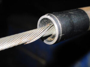
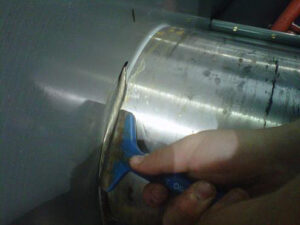
As a part of regular maintenance, cased hole wireline cables need to be “cut back” to remove portions of the cable that either have excess diameter reduction or where the armor wires have become brittle. Although diameter reduction and loss of ductility (embrittlement) often coincide, they are independent. Diameter reduction is the result of mechanical friction or plastic embedment. At the same time, loss of ductility results from a chemical attack resulting in an alteration of the microscopic structure of the steel.
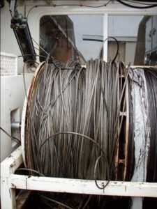
Electromechanical wireline cables are subjected to tension and wear whenever they enter a well bore. Vertical wells are the best-case scenario for minimum wear and drag, but even the most ideal vertical wells have deviations. The cable will rub against the sheaves, measuring head, casing, and flow tubes, causing friction between the two metals and reducing the cable diameter.
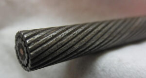
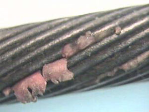
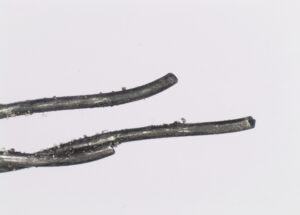
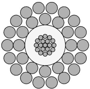
With the advent of horizontal wells and pump-down applications, cable wear and tensions have increased significantly. As a cable wears, its diameter decreases due to the outer armor wires flattening and getting smaller, as shown in the pictures below.
This loss in outer armor wire diameter results in
1) reduction of the overall breaking strength of the cable,
2) the weak point at the cable head becoming unknown due to both the reduction in wire strength and the potential for slipping inside cone-style cable heads and
3) a poor grease seal and difficulty sizing flow tubes during pressure work.
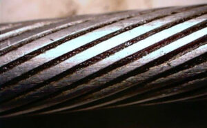
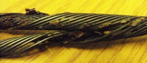
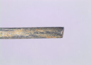
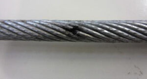
Diameter loss can also occur when you subject a cable to very high tension, which happens more today than in years gone by due to the complex well geometries and depths. At very high tensions, the wires will embed into the plastic, creating a smaller overall cable diameter, as shown in the picture below. Although this does not reduce cable strength, it can create issues related to adequately sizing flow tubes and potentially contribute to prematurely electrically shorting the cable.
Diameter loss can also occur when you subject a cable to very high tension, which happens more today than in years gone by due to the complex well geometries and depths. At very high tensions, the wires will embed into the plastic, creating a smaller overall cable diameter, as shown in the picture below. Although this does not reduce cable strength, it can create issues related to adequately sizing flow tubes and potentially contribute to prematurely electrically shorting the cable.
Over time, a cable will become tapered where the diameter at the tool end is smaller than the diameter farther up the cable, which can result in difficulty getting a proper grease seal through the flow tubes. It is important to understand the diameter over the entire working length of the cable to ensure that problems related to sizing flow tubes do not occur. We highly recommend that cable diameters along the cable length be measured frequently and recorded in the cable record book by a qualified distributor.
Cased hole wireline companies generally work in several fields for oil and gas companies. Every oil and gas company has specific operational practices for drilling, completing, and stimulating production. These practices involve many different chemicals, including some that hurt the life of a wireline cable. In addition to the manufactured chemicals in the wellbore, naturally occurring chemicals and gases negatively affect GIPS wireline, including hydrogen sulfide, carbon dioxide, and chlorides. Because wireline companies operate in many different wells, and knowledge of well conditions is only sometimes well known, the potential for corrosion or embrittlement can be high.
Today’s operational environments demand that everyday work practices include regular inspections for diameter loss and loss of ductility. You should perform inspections whenever re-heading unless operating in a well-known environment. As shown in the picture below, the wires are bent around the cone during re-heading, creating a stress concentration. These stress concentrations are susceptible to corrosion and cracking. After re-heading, grease must be applied inside the cable head covering these bent wires.
Routine wireline inspections should include the following:
» Visual examination of the whip end for any mechanical damage. » Measurement of the outer armor wires for wear and ovality. » A test for ductility.
If operating in an area known to have the potential for any chemical attack, perform re-heading and the wrap test more frequently. These tests only take a few minutes and could prevent a significant cable problem. Follow the procedures for measuring wear and ductility outlined below.
Testing for Wear:
1) Cut back 50 feet of cable from the whip end.
2) Inspect a two-foot sample for mechanical damage or unusual properties.
3) Remove the outer armor wires.
4) Clean the outer armor wires.
5) Using a set of dial calipers (micrometer or vernier calipers), measure the diameter of the individual wires at the narrowest point (flat spot) and the widest point. We recommend a minimum of six wires.
6) If the wire has lost 12%-15% of its original diameter, cut back the cable further.
7) Cut back 100-150 feet and re-inspect by following steps 2 through 6.
Testing for Ductility:
Once the cable is verified to have an acceptable amount of metal left on the outer armors, perform the ductility test as follows:
1) Cut approximately one foot from the wire sample.
2) Bend about 3 inches of the wire 90 degrees and place the short end in a vice.
3) Wrap the long end around the diameter of the short end tightly, making slow turns.
4) After making five complete wraps, slowly unwrap the wire.
5) Inspect for any breaks or cracks.
6) If the wire breaks or cracks, cut back and re-test by repeating steps 2 through 5.
We address these issues and field equipment to use for testing and recording test data electronically in our cable schools. Please call your local Quality Wireline sales representative to learn more.
The oil and gas industry exposes manufacturers and service companies to some of the most challenging environments. During wireline operations, cables routinely run tens of thousands of feet below the earth’s surface, exposing the tools and the cable to pressures over 10,000 psi and temperatures over 400°F, all the while transmitting clean, reliable data. In certain wellbore environments, the temperatures can reach over 600°F, challenging the limits of current technology. This article discusses the effect of temperature on wireline cable and how to ensure success under the most challenging operating conditions.
The maximum well temperature of a cable exposed under ideal conditions defines the temperature rating of wireline cables. Ideal conditions include operating in a vertical well, normal tension profiles, tight armor, and other factors. In the oil and gas industry, downhole operations are seldom ideal, and during pump-down operations, the conditions are even further from ideal. There are so many variables related to cable selection that it is best to rely on field experience in conjunction with input from experts in the manufacturing and operation of wirelines.
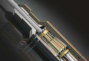
Common knowledge suggests that the plastic is the determining factor in the temperature rating of a cable. Three circumstances, or typically a combination of all three, cause the plastic to deform: tension, temperature, and time. Tension increases the radial compressive forces exerted by the armor on the core (conductor), squeezing the plastic core. If the combination of temperature and tension is high enough, the plastic will exude (ooze) through the inner armor wires over time, as depicted in the photo (above left). Plastic selection is crucial; however, other factors will dramatically increase operational life at elevated temperatures, including: 1) Manufacturing Quality, 2) Cable Conditions, 3) Materials Selection, and 4) Operating Conditions.
Manufacturing Quality
Starting with a good quality product is critical in ensuring the cable will hold up long-term under the challenging conditions that the wireline is exposed to daily. Most wireline manufacturers have similar designs, but the manufacturing processes and quality control vary considerably. The two areas of manufacturing that will impact a wireline’s performance at elevated temperature and tensile loads are the core (conductor) quality and the inner armor coverage.
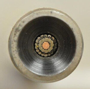
The Core
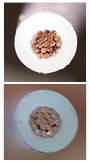
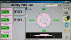
The copper has to be perfectly centered in the core to ensure the maximum amount of plastic insulation separates the armor wires from the copper (top photo). Having a concentric core is critical as the armor squeezes into the plastic. Even today, to check concentricity, many manufacturers cut and inspect both ends of the conductor and assume the 20,000 to 100,000 feet of extruded core between the ends remains consistent. This assumption can result in a section of the core not centered going unnoticed, as shown in the bottom photo. Quality Wireline and Cable uses leading-edge ultra-sonic technology to measure the concentricity 480 times per foot, ensuring the best possible success in critical well operations. The depiction below shows the concentricity device and operator screen controls.
Inner Armor Coverage
Inner armor coverage refers to how much of the core is covered by the inner armor wires. Traditionally, an acceptable range for inner armor coverage would be 97.5% to 99.5%. Higher coverage results in a stiff cable and lower coverage results in problems with plastic prematurely exuding through the inner armor wire (right photo), resulting in loose armor or, in extreme cases, premature electrical failure.
The first step in ensuring perfect coverage is a perfect core (conductor). The core must be held within a very stringent diameter and ovality control (<0.001”) to attain precise and consistent inner armor coverage during the armoring process. In addition to three separate laser scanners measuring diameter and ovality, Quality Wireline and Cable uses laser lump detection technology to find any potential defect before the cable goes to the field. Quality Wireline and Cable takes precision manufacturing one step further to achieve the ideal coverage of 98.5% through the implementation of synchronous smart electrical drives on tubular stranding machines. This leading-edge technology eliminates the mechanical gearbox and allows infinite coverage precision, resulting in as close to a perfect cable as possible.
Cable Conditions
Because of today’s changing operational practices, including pump-down operations, wireline cables often work under non-ideal conditions that cause the armor to become loose. When the outer armor wires loosen, the inner armor tightens, and the tensile load is transferred from the outer armor wires to the inner armor wires, resulting in abnormally high radial compressive forces on the core. This squeezing of the core (conductor) causes the armor wires to embed further into the plastic, slowly pushing the plastic out between the armor wires. When the plastic is soft at higher temperatures, this squeezing occurs faster. For maximum life from a wireline cable and to operate successfully in high-temperature environments, it is vital to keep the armor tight by servicing it when required.
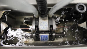
The photo above shows a twister used to tighten the cable. For basic information on loose outer armor and how to determine when the armor is loose, refer to Technical Bulletin 3, available at f-e-t.com/qualitywireline.
Materials Selection
Material selection is critical to ensure the finished wireline performs as designed. Generally, we think of “plastic selection” when considering material choice regarding high-temperature wireline. However, wellbore temperatures can affect the mechanical properties of the armor, as well.
Type of Plastic
Three circumstances cause the plastic to deform: tension, temperature, and time, typically a combination of all three. As tension increases, the radial compressive forces exerted by the armor on the core (conductor) increase, squeezing the plastic core.
If the combination of temperature and tension is high enough, the plastic will exude (squeeze) through the inner armor wires over time, as depicted in the top photo. The lower photo shows a phenomenon called “snakeskin,” where the plastic forms a thin layer between the two armors. This “snakeskin” peels away when removing the outer armor. This loss of plastic on the conductor can result in loose armor and a higher risk of electrical failure.
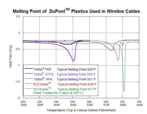
The first step to prevent any exuding is selecting the best application material. The top image in the right column shows the most common DuPontTM materials and their respective melting points for high-temperature wireline applications. Although the melting point of plastics is important, understanding the exuding as a function of temperature, tensile loads, and time is critical. Quality Wireline developed a test apparatus that subjects wirelines to temperatures under high tensile loads simulating downhole conditions. Using the “exuding test” is essential in ensuring operational success before entering high-temperature environments with unknown elements.
Temperature ratings of plastics for wireline cable have been derived primarily from years of operational experience. That is not to say that plenty of science has yet to go into developing and testing these cables. Quality Wireline’s proprietary “Exuding Tester” helps further understand the impact of radial compressive loads on the plastic core as the wireline is exposed to high tensions at elevated temperatures. This test device was instrumental in evaluating and comparing the new 600°F plastic (Q600) before field trials. Furthermore, you can use it to evaluate wireline at any combination of temperature, exposure time, and tensile load.
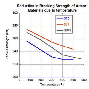
Type of Armor
Temperature affects the mechanical properties of GIPS and alloys used for wireline armor, as depicted in the figure on the next page. It is important to understand that wireline cables can lose up to 12% of their breaking strength due to wellbore temperature. Under certain combinations of temperature and tensile loads, the plastic may be suitable where the armor cannot provide the strength required to perform the wireline operations. Understanding potential limitations is paramount before starting operations at high temperatures.
In addition to the loss of strength at elevated temperatures, heat acts as an aggressive catalyst to the corrosion process. In lab studies of high-carbon steel, the corrosion rate doubles every 20°F. Well fluids, in combination with temperature and pressure, are the only accurate way to ensure that you have the correct material for the application, which is also true for both GIPS and alloy applications.
Selecting the appropriate material for sour service lines is best done by applying a quality software program combined with personnel experienced with sour service cables and their application.
Operating Conditions
Regarding the temperature effect on wireline, the three most important factors from an operating perspective are understanding the tension profile, temperature profile, and exposure time.
Temperature Profile
In general, the earth has a temperature gradient that is well known and is inconsistent from one geographic region to the next. For example, the bottom hole temperature at 12,000 feet in Texas can range from 120°F to 320°F. Flowing wells in production testing applications will change the natural temperature gradient; uphole wellbore temperatures become much hotter than the thermal gradient would predict. Even stranger, the temperature gradient in steam injection and SAGD (Steam Assisted Gravity Drainage) wells can be upside down, where the hottest part of the wellbore is the wellhead and the coolest part is the bottom hole.
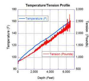
Tension Profile
Typical tension profiles for an ideal vertical well have the full weight of tools and cable at the top of the well, which drops to the weight of the tool at the bottom, similar to the profile shown below. Today, a large percentage of wells are deviated or horizontal, which changes the ideal tension profiles. Abnormal well conditions, pump-down operations, excessive tool drag, stuck tools, or the tool or cable being differentially stuck will result in the tension profile changing dramatically and a higher percentage of the full load moving to a point in the cable different from the drum or wellhead.
In an ideal well, the highest tensions are at the lowest temperatures, and the lowest tensions are at the highest temperatures. With the growth of the horizontal market and advancements in thermal technologies today, this is only sometimes the case. Combining the higher temperatures with higher tensions creates a challenging environment for the wireline and one that the operator needs to be aware of.
Exposure Time
As the wireline enters the wellbore, it increases in temperature over time. For example, in a dry gas well, it takes about one hour for the core of a 9/32-inch cable to increase in temperature from 60°F to 450°F. The same cable in a fluid-filled well may heat up in several minutes. If you can perform the operations in less time, the plastic remains hard, and there is less potential for damage to the cable. In most wells, the time duration of exposure to the cable at the highest temperature is the least because this peak temperature occurs at the deepest part of the well. However, this is not always the case, as previously discussed. Understanding the relationship between time, temperature, and tension helps to ensure you select the best cable for your operations.
To achieve the most extended life from cables operating under elevated temperatures, it is imperative that you first start with a manufacturer that understands the intricacies of working in these harsh environments and has invested in the equipment and expertise to manufacture the best possible product. Combining field experience with manufacturing expertise to select the best cable to meet your operating parameters and ensuring the cable remains in excellent working condition are key to success. Quality’s constant development of process improvements, unique synchronous drive system, advanced extrusion system, and search for new and improved products have kept Quality at the forefront of higher success in deep/hot challenging wellbore environments.
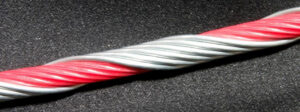
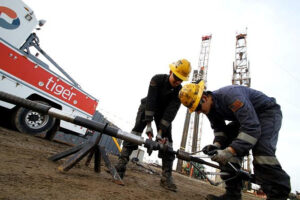
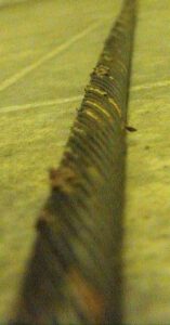
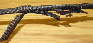
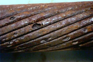
Downhole wellbore environments can contain some nasty, corrosive fluids and gases, most commonly Hydrogen Sulphide and Carbon Dioxide. Hydrogen Sulphide (H2S) aggressively attacks the iron in metal, causing pitting and stress cracking, as depicted in the picture below.
In the case of a standard GIPS wireline (Galvanized Improved Plow Steel), the H2S initially reacts with the zinc coating (galvanization) and then attacks the steel wire. As shown below, the wire can become as brittle as a glass rod in high enough concentrations.
Under these circumstances, it can be challenging to retrieve the cable because the armor strands can break as they go over the sheave or through the flow tubes, resulting in the possibility of dropping tools downhole. In addition, on rare occasions, the H2S will permeate the plastic and quickly destroy the copper conductor, resulting in an electrical short of the cable. Most of us have either heard or experienced stories similar to this. The age-old questions include: 1) Where can I use a GIPS cable, and 2) When do I have to use a sour service alloy cable?
Broken armor wire from H2S embrittlement
Most wire manufacturers will tell you there is no safe limit for using a GIPS wire in a sour gas well, which is a good recommendation. However, we all know that GIPS cables are used regularly in wells containing low amounts of H2S and other corrosive conditions in the oil and gas industry. Under corrosive conditions, it is imperative to use a corrosion inhibitor to protect the cable. Operating a GIPS cable under any corrosive conditions is typically done in cases where the wireline operators are familiar with the field and have seen little or no effect on the structural integrity of the wireline. Again, the question arises: How do I know that without the experience?
This question is difficult to answer due to the many factors influencing how corrosive the fluids in a particular well will be. The factors in the list below accelerate the chemical reaction. Together, many act as a catalyst, increasing the corrosive nature of the fluid or gas.
▪ H2S (ppm)
▪ Chlorides (ppm)
▪ CO2 (%)
▪ Wellbore Temperature
▪ Exposure Time
▪ Wellbore Pressure
▪ Water Cut
▪ Acid
▪ pH
There is software that can predict the corrosive nature of the fluid on a relative basis, whereby you can determine what material to use in a particular well. However, like all software, the output is only as good as the input. It is often difficult to assess current fluid analyses from a well, or the information, at best, is an educated guess based on data from nearby wells. In some cases, the information is completely inaccurate. Many times, the corrosive effects of the well will not manifest for several days, making it very difficult to go back to the well’s owner for compensation.
The most current, accurate information is essential when deciding whether to use a GIPS cable. If you trust the information, some “old school rules of thumb” may be used. Typically, the people using these “rules of thumb” have some experiential knowledge that compliments the formulae.
Below, the two most common “rules of thumb” are noted separately for H2S and CO2:
CONCENTRATION OF H2S
If H2S (ppm) X BHP = 0.05 or greater do not use GIPS
Example:
H2S = 8ppm = .000008 or 8 x 10 -6
Bottom Hole Pressure = 6,000 psi
TEST: 0.000008 x 6,000 = 0.048
In this example, a GIPS cable may be suitable.
CONCENTRATION OFCO2
If Percent CO2 x BHP(psi) = 130 or greater do not use GIPS
Example:
CO2 = 2% = 0.02
Bottom Hole Pressure = 6,000 psi
TEST: 0.02 x 6,000 = 120
In this example, a GIPS cable may be suitable.
Note: Remember that these “rules of thumb” do not consider all of the factors discussed earlier and should only be used in conjunction with field knowledge. We strongly recommend using good protective grease on a well-seasoned line if using a GIPS cable in any corrosive environment.
The armor wires of wireline cable typically come in four materials:
● GIPS
● S77 (UNS S31277)
● S75 (UNS N08926)
● MP35 (UNS R30035)
GIPS is your standard everyday wireline, while S75 and S77 are alloy lines containing a smaller amount of iron, making them less vulnerable to attack by corrosive fluids and gasses. MP35 is an alloy with almost no iron and is highly resilient to most hostile chemicals found in downhole oil and gas environments.
All sour service cables use a nickel-plated copper conductor, which is very resistant to corrosive fluids. You must select a sour service cable if you cannot use a GIPS cable. Selecting the appropriate material for sour service lines is best done by applying a quality software program combined with personnel experienced with sour service cables and their application.
Fitting with the topic, we provide a disclaimer: This article’s information is purely advisory. In no event shall FET|Quality Wireline or its employees be liable for any damages, including but not limited to consequential damages arising from or in connection with any person’s use of this technical bulletin.
From a cable manufacturer’s perspective, this technical bulletin intends to look at best practices on pressure work for longer cable life.
Many energy companies perform wireline operations when the well is “live” or the wellbore pressure exceeds the atmospheric pressure. There are several reasons for performing live operations, including
» lowering the cost of operations, » reducing formation damage, » minimizing lost production due to downtime and » performing pump-down operations.
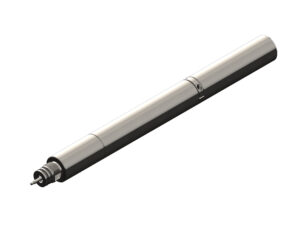
By design, armored lines (aka wirelines) have interstices between armor wires and armor layers, which you cannot pack off directly. A grease head and lubricator are employed to maintain well control during “live” operations. Before the rope socket is attached, the wireline passes through several closely fitting flow tubes (pictured below).
Viscous grease is injected into the assembly at pressures exceeding wellbore pressure and fills the space between the wireline and the inner diameter of the flow tubes. The grease packed in the tight annular space provides significant resistance to wellbore pressure by adhering to the surfaces of the cable and the flow tubes while permitting the wireline cable to travel into and out of the wellbore. Each subsequent flow tube creates a compounding pressure drop, so there is no residual pressure drop as the wireline exits the flow tube. Pressure is maintained higher than wellbore pressure with a grease pump. The tighter the annular space, the higher the force (pressure) required to displace the grease. This principle is the same for both braided wireline and slickline.
A pack-off is mounted at the top of the lubricator to seal the well in case of losing pressure control through the grease head. It should not be used as a line wiper because the packing rubbers are harder and can cause damage to the wireline. These devices also prevent the wireline from rotating, which causes the armor to loosen and may result in a birdcage below the pack-off. Additionally, wear on the pack-off rubbers can limit their ability to seal the wireline effectively if the flow tubes cannot hold back the wellbore pressure. In reality, many operators use the pack-off to wipe the line, specifically when the flow tubes are oversized, and pressure control with grease is difficult to maintain.
The argument for wiping the line is that the wireline equipment and well site stay clean, providing a better work area and more responsible environmental stewardship. More and more operators working offshore and in environmentally sensitive regions require line wipers. If you require or plan to use a line wiper, we highly suggest using one in addition to the pack-off. In other words, do not use the pack-off for this purpose.
You can purchase supplemental line wipers with softer rubber. A proper setup will allow the pressure on the line wiper to have more sensitive control than a pack-off to minimize the force on the wireline. Never use the line wiper to control pressure; their only use is to clean the line. However, the user should always be aware that there is the possibility of damaging the wireline when using a line wiper.
New Cables
New cables can be risky for pressure work because the cable is subjected to only a few hundred pounds of tension during manufacture, so there is essentially no torque in a new cable as delivered. When installed on a truck, the spooling tensions are significantly higher than during manufacturing. Because the cable is not free to rotate, it will develop significant torque and try to rotate to equalize this built-up torque and support the weight of the tool string when making the first field operations.
To illustrate the magnitude of this problem, consider a new 7/32-in. cable deployed in a straight 20,000-ft. well. The total rotations a new cable end would need to rotate to equalize the torque could be over 400. Until the cable is well “seasoned,” we recommend that flow tubes be on the high end of the industry standard (0.004 to 0.006 of an inch) to allow for line diameter and cable rotation changes. This “seasoning” is critical to the life of a wireline cable, and we recommend reviewing Technical Bulletin 2―New Cables: Understanding the Issues and Tips for Longevity, which discusses line speeds and operational practices for new cables.
Pressure work also slows the seasoning process by lubricating the cable and preventing grit and corrosion from forming in the armor’s spaces. This wellbore fluid and grit, combined with corrosion, helps prevent the cable from spinning, which is important in seasoning. Once seasoned, the lubrications from grease jobs are good for the cable. You will require a substantial amount of extra grease to fill the interstices between the armors the first time you use a cable for grease injection.
Always use new flow tubes on new cables. Used flow tubes may have wear, and it is not necessarily even around the diameter of the flow tube. This non-uniform wear can cause a high friction spot in the flow tubes and a non-uniform annulus between the flow tube and cable. These circumstances are not worth risking cable damage, particularly on a newer cable, when you should anticipate additional spin and changes in diameter.
Sizing Flow Tubes
Before starting a pressure job, it is essential to understand the diameter of the cable and the amount of wear on the cable. Generally, it is a good idea to measure the wireline with a caliper every 2,000 feet and record the readings in the line record book for future reference when selecting flow tubes. A good rule of thumb is that if the wireline varies in diameter by more than 0.006 inches, it is not a good candidate for pressure work. If you are running deeper than usual or the line has been cut off or shortened, you could be getting to a part of the wireline that has never been off the drum, the same as a new cable. Now, you have a mixture of used seasoned cable and brand-new cable. You must treat it as if the cable is new.
The industry standard for flow tube selection has been 0.004 to 0.006 inches larger than the maximum OD of the wireline entering the well. A wireline cable will vary in size along the entire cable length due primarily to wear and stretch. Flow tubes also wear, causing their inside diameter to increase in size. Understanding your cable and flow tube diameters is critical in getting a good seal during pressure work without compromising the possibility of getting stuck in the flow tubes and potentially breaking the cable.
Crossed Armor Wires
A common problem with using flow tubes that often go unnoticed is “crossed” armor wires. To insert the wireline through the flow tubes, cut off the rope socket and twist the armor wires together. During this step, the armor wire gets crossed unintentionally, as shown in the picture below. This crossed armor may cause problems by getting stuck in the flow tubes on that first run. Or it may get milked up the cable and then show up many runs later thousands of feet up the cable.
The crossed armor wire could also be forced back through the flow tubes by indenting the outer armor into the inner armor and plastic conductor, again going unnoticed. In this case, however, by its very nature, the crossed armor will take most of the wear as the wireline slides through the flow tubes. Eventually, the wire will break and potentially ball up below the flow tubes. This condition, where the inner wire forces through the plastic to the copper, can also result in an electrical short.
The best practice to prevent crossed armors is to stop and check the cable after installing the first flow tube. Slide the first tube back and forth, then run your hand down the cable in front of the flow tube, feeling for any irregularities. If you find a crossed armor wire near the tool end that was not forced through the flow tubes, you can sometimes milk it back to the tool end. However, if the crossed wire is hundreds or thousands of feet up the wireline, the best practice would be to go to the nearest authorized service center to have them return the wireline to operational condition. When a crossed armor has been forced through a flow tube and found, you must cut off the wireline to prevent the possibility of either a broken armor or electrically shorted cable.
Sinker Bars
To enter a live well, you must overcome the force of the well’s pressure by adding sinker bars to the end of the tool string. You can calculate the weight of the sinker bar using the formulae below or go to www.qualitywireline.com and use the sinker bar calculator under “technical support.”
The force pushing the cable out of the well is a function of the pressure in the well and the cross-sectional area of the wireline. Use the following calculations:
Cross-Sectional Area
Where r is the cable radius, and π (Pi) is 3.14
Example:
Wireline 7/32 in. (0.224 in.) with tool string weight (T) of 175 pounds
r 0.224/2 0.112 in.
.14 0.112
A = 0.0394 in.2
The Balance Weight F = P x A
If the wellbore pressure (P) is 7,500 psi
F = 7,500 psi x 0.0394 in.2
F = 295 pounds
This force or balance weight will counterbalance the wellbore pressure. For pulling the wireline into the well, apply an additional weight (overbalance). Generally, that is about 20% of the force, but each operator may have their own rules of thumb.
Ft = F + (20% x F) = 295 + (0.2 x 295) = 354 pounds
Sinker Bar Weight = Ft – T = 354 – 175 = 179 pounds
The wireline sheave is an integral part of wireline operations and much more critical in extending the life of a wireline than many people know. Using an inappropriately sized sheave for a wireline all too often damages the wireline, usually occurring after just one run in the well! Typical types of damage include stresses putting the wireline out of round, loose outer armor, broken strands, and ultimately reduced breaking strength of the wireline. You can easily avoid these problems with some basic and essential education on marrying the correct sheave with each wireline.
We realize there are many reasons why some people select one manufacturer or style of sheaves over the other; however, from a wireline manufacturer’s perspective, two characteristics of a sheave matter most: 1) groove design and 2) diameter. Let’s look at what can happen with a wireline due to each sheave characteristic.
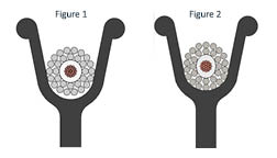
Sheave Groove Design: What Can Go Wrong
Figures 1 and 2 illustrate a wireline using a sheave with a groove diameter that is too small. As you can see in the relaxed state of Figure 1, the wireline rides on the edges of the sheave because it is not appropriately cradled.
When applying tension in Figure 2, the wireline pulls down into the groove and deforms to the shape of the groove. This permanent deformation can result in an “out of round” wireline where several issues can occur, including:
Problems getting through flow tubes on pressure work,
Problems when trying to spool the cable back onto the drum correctly and
Excessive wear on both the cable and the sheave.
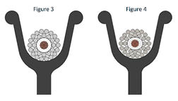
Figures 3 and 4 depict a sheave with a groove diameter too large for the wireline. Figure 3 shows a wireline in a relaxed state resting at the bottom of the sheave groove without touching the sides for support.
When applying tension in Figure 4, the wireline flattens into the groove and can permanently deform, causing:
Problems getting through flow tubes,
Spooling trouble, and
Prematurely wearing a track in the sheave.
Sheave Diameter: What Can Go Wrong
If you have ever bent a wire back and forth until it breaks, you have experienced “yielding” and “work hardening” of steel. When you bend a wire at too sharp of a radius, the stresses on the edge of the wire increase beyond the yield strength of the material; in other words, you have permanently deformed the wire. Each time you “yield” the wire this way, it becomes slightly longer. As you continue to do this through several cycles, the metal “work hardens” and becomes increasingly brittle until the stress on the wire exceeds the ultimate tensile strength, and it snaps. The same is valid with wireline.
The smaller the sheave, the higher the stress applied to the wireline. If the wireline travels around a sheave, creating too tight of a bend, the armor on the outside of the bend gets stretched. As the wireline straightens, these outer wires are more extended, resulting in loose armor. Loose armor can accumulate below the flow tubes, resulting in a bird cage and the need to kill the well to remove the wireline. If allowed to continue, the wires “work harden” and eventually fail.
Catalysts that contribute to work hardening include:
Number of cycles
Type of alloy (how hard it is to begin with)
Presence of chemicals (many cause the wire to be more brittle)
Diameter of the outer armor wires (plays a crucial role in total stress)
Sheave diameter
Load on the wireline combined with the bending stress
Selecting the Right Wireline Sheave
In most operations, the sheave groove size and shape are far more critical than the sheave diameter. However, the proper sheave diameter must be used in applications where the wireline will have high tensile loads. Diameter and groove design are essential parameters on every sheave but even more critical on the top sheave, where the wireline travels around the sheave 180 degrees. In contrast, generally, on the bottom sheave, you are at a 90-degree angle with less contact with the wireline on the sheave.
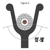
Groove Diameter: Figure 5 shows an appropriately sized sheave for the wireline. Cradling the wireline supports the side loads, and the shape of the wireline will remain constant under tension.
Note: » Proper grove diameter: 1.0 to 1.04 wireline diameter » Proper grove shape: 135 to 150 degrees of support as depicted in Figure 5.
Sheave Diameter: Typical industry guidelines are: » Depth <25,000 feet (8,000m), minimum sheave diameter is 400 times the outer armor wire diameter (not the wireline) » Depths >25,000 feet or high loads, the minimum sheave diameter is 600 times the outer armor wire diameter
Example:
5/16-inch cable – outer armor wire is 0.0445 inch
The minimum sheave diameter for normal operations less than 25,000 ft. equals 0.0445 inches * 400 = 17.8 inches (18-inch sheave)
Following these simple guidelines will extend the life of the wireline and the sheave. A few last pointers include:
» Do not use the same sheave for multiple diameters of wireline. » The bigger the diameter sheave, the less stress is applied to the wireline, and it will help to extend the cycles or runs that this wireline can perform. » Ensure proper alignment of sheave and truck to prevent loosening of the armor.
This technical bulletin aims to provide a basic understanding of electrical leaks and a procedure for field personnel to identify the type and location of an electrical leak and, if possible, keep the wireline unit working.
Although locating electrical leaks can be complicated, a skilled operator can resolve most problems in the field using a good quality ohmmeter that reads to 1/10 Ohm, saving a trip to the service center and allowing the wireline unit and crew to finish the job.
Typical steps to identify electrical leaks are:
1)Tool String – Testing the tool string is the simplest and easiest repair in the field, as you can usually find spare tools on the wireline unit. If the spare tool works, this was likely the problem.
2)Cable Head – If the tool string checks out well, the next step is to check for problems in the cable head, where most electrical leak-related issues occur and are typically due to human error. To check the cable head, cut the cable just above the cable head and test the electrical integrity of the head. If you locate the fault, rebuild the cable head and reattach the tool.
3)Collector (Slip) Rings – Many electrical problems occur in the collector rings, the coaxial cable going from the collector rings to the control panel, and occasionally the control panel. Loose wires, corrosion, wear, pressure washing or steaming the unit, and faulty equipment contribute to these problems.
a. If the leak still exists after testing the cable head, disconnect the collector ring from the cable and test the electrical integrity of the ring through to the panel.
b. If there is a problem, disconnect the coaxial cable from the collector rings and test the collector ring independently.
c. If the collector ring is good, disconnect the coaxial cable’s other side from the control panel and test the coaxial cable. Test the control panel next if the problem is not in the coaxial cable.
4)Wireline – If the electrical problem was not in the collector ring to the control panel, test the wireline before progressing to the coaxial cable and control panel. The most common areas where wireline problems occur are:
a. Working Part of the Cable – Physical damage during rigging up, not using a gooseneck, perforating kickback, jumping sheaves, excessive temperature, excessive tension, offset conductor, or broken inner armor contribute to failures in this part of the cable.
b. Drum End of the Cable – Drum crush, installation problems, and failure at the drum entry hole are common causes of failure.
Understanding the typical causes of leaks and shorts will speed up the investigation process. Leaks can occur in many forms, each with unique challenges in locating the leak. The common leak types, which can happen in the tool string, cable head, collector rings, or wireline, include:
Dead Short – The conductor is in direct contact with the armor; this is the simplest type of short to locate.
Intermittent – This is the most challenging type of leak because it is not always apparent.
High Resistance – Leaks where the leak resistance is much greater than the conductor resistance can be challenging to locate.
Wet Leaks – Occur when there is moisture in the leak. Saltwater complicates wireline leaks because it causes a small voltage between the copper conductor and the zinc coating on the armor wire. This potential will create misleading resistance readings, and accurate leak location in the field is impossible.
Multiple Leaks – Occur when a wireline has several leaks. The cable located to the right likely has more than one electrical leak.
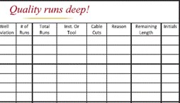
If the problem lies within the wireline, determining where the leak is relative to the tool determines the possibility of making repairs in the field. Although there are several ways to identify electrical leaks in the wireline, only one method can be used effectively in the field. Regardless of the measurement technique, cable length must be known, recorded accurately, and maintained in cable record books.
It is imperative to maintain accurate cable record books.
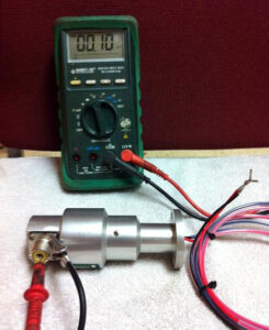
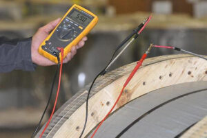
The dead short leak is the only type you can effectively deal with in the field. A good quality ohmmeter (Fluke) that reads to a minimum of 0.1 Ohms is essential in determining if you have a dead short leak. Use the following methodology to test for a dead short:
1) The first step is to short your meter leads and record this resistance reading. Subtract this lead resistance from all resistance measurements to eliminate errors due to the resistance of the leads.
2) Disconnect both cable ends and ensure the leads are clean.
3) Measure the resistance of the conductor to ground (armor) on the whip end Rw.
4) Reverse the leads and again measure Rw. If the resistance significantly differs with the leads switched, you have a wet leak and a precise location in the field is impossible. Proceed to step 7. If the readings are the same, proceed to step 5.
5) Measure the resistance of the conductor to ground (armor) on the drum end Rd.
6) If the leak is not wet, use the formula below to determine if you have a dead short, where Rc is the resistance of the current length of the conductor (from the cable record book).
If the value of Rc in the cable record book is questionable, measure the conductor resistance.
If (Rd + Rw – Rc) < 300 Ω, you have a dead short; otherwise, you have a high resistance leak. If you have a dead short, skip step 7.
7) If there is a high resistance or wet leak, the next step before going to a service center is to unwind several hundred feet of cable and, with the Ohm meter attached at the drum end, watch the Ohm meter as this loose cable flexes along the length by hand. It is a crude but sometimes very effective way of leak location as many cable leaks occur within a few hundred feet of the whip end. After finding the leak, cut the cable and test. If the leak is still present, you must take the cable to a service center.
If the resistance is less than 300 Ω, follow these steps to determine the leak’s location.
1) Find the cable’s total length (L) from the cable record book.
2) Calculate the cable length to the leak from the whip end (Lw) using the following formula:
Lw = (Rc + Rw – Rd) x (L / (2 x Rc))
3) Calculate the cable length to the leak from the drum end (Ld) using the following formula:
Ld = (Rc + Rd – Rw) x (L / (2 x Rc))
This example shows how to use the formulae:
L = 24,500 ft. (7,468 m)
(For metric, use meters in the same formulae)
Rc = 68.6 Ω
Rw = 149.4 Ω
Rd = 205.2 Ω
First, test to see if it is considered a dead short: (Rd + Rw – Rc) = 286.0 Ω Less than 300 Ω
Check leak distance from the whip end: Lw = (68.6 + 149.4 – 205.2) x (24,500 / (2 x 68.6)) = 2,286 ft.
Check leak distance from the drum end: Ld = (68.6 + 205.2 – 149.4) x (24,500 / (2 x 68.6)) = 22,214 ft.
Once you have located the leak, slack the cable, examine it for physical damage, and manually flex it while observing the leakage resistance. You should find variations in the ohmmeter reading if you are at the leak. If the leak is close enough to the whip end that you can spool down and cut off, and you have enough cable remaining to perform the current services, then do so. After cutting out the short, test the remaining cable to ensure electrical integrity. Re-head and finish the job.
If the leak is too far from the whip end to cut out, you must take the cable to a service center for inspection. At a service center, they are well-equipped to deal with all types of leaks. Burning a leak out with a “burn-out” box is the fastest way to identify difficult leaks. The service center will also have more sophisticated equipment than an ohm meter to try and locate the exact point of failure. If the service center suspects the damaged cable is from mechanical damage or temperature, a burn-out box will save time finding the leak. However, if it is essential to determine the cause of the leak, then do not use a burn-out box as it will destroy the area around the leak and likely make it impossible to perform a root cause analysis of the failure.
Note: This picture shows the damage to the conductor and the armor as a result of using a burn-out box.
There are many times when there is a need to verify the cable. Some reasons include: » when removing the cut cable, being unclear about its length, » verification of the cable record book, » checking a cable length in the yard or » just being sure you have enough line to get to the bottom.
Whatever the reason, having a quick, easy, and accurate means of determining the cable length is invaluable. This technical bulletin outlines the formulae for accurately determining the length using only an ohm meter and access to both ends of the cable.
For best results, use a good quality meter with 5-digit resolution, and follow these steps:
Short the meter test leads and record this resistance: RL (Ω).
Measure end-to-end cable conductor resistance plus the test leads resistance: RM (Ω).
Total cable conductor resistance is RT = (RM – RL) at shop temperature (Ω).
Listed on the final inspection report supplied with cable is RK, which is the cable resistance /1000 ft. @ 68°F.
Calculate cable length:
L = (RT / RK) x (458 / (390 + T)) x 1000
L = Length of the cable in feet
-390°F is the inferred zero resistance temperature
T = Shop temperature at the cable location (°F)
Metric Formulae:
L = (RT / RK) x (254 / (234 + T)) x 1000
L = Length of the cable in meters
T = Shop temperature at the cable location (°C)
RK = is the resistance of the center conductor per km at 20°C
Example: 1-A-224-12/18-G (Sample Cable)
RL= 1.50 Ohms
RM= 64.65 Ohms
RT = 64.65 – 1.50 = 63.15 Ω
RK = 4.11 Ω/1000 ft.
T = 42°F
L = (RT / RK) x (458/(390+T) x (1000)
L = (63.15/4.11) x (458/(390+42)) x (1000) L = 16,280 feet, length of the cable
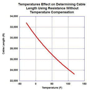
The component of the imperial formulae (458/(390+T)) is used to temperature compensate the resistance back to 68°F where “RK” was calculated. The cable length error could be very significant if the temperature compensation was not performed. The graph on the following page shows the error in cable length that could occur due to not temperature compensating. The example is a 7/32-in. mono-conductor, 25,860 ft. in length. Determining the length if temperature compensation was not accounted for would range from 23,000 ft. at 110°F in the summer heat to 33,000 ft. in northern winters. Clearly, the error is not insignificant.
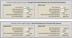
1) An average value of “RK” (DC Conductor Resistance) found on the cable spec sheet should only be used if the actual calculated values cannot be found.
2) Each Quality cable comes with a Quality Certificate which contains the actual value of “RK” as determined at the manufacturing plant.
3) When the cable is first purchased and installed, the resistance (Ri), length (Li), and temperature (Ti) should be recorded in the cable record book, and “r” should be calculated using the following formulae:
RK = (Ri / Li) x 458 / (390 + Ti) x 1000
Example:
Li = 25,100 ft Ri = 260.2 Ω Ti = 77°F
RK = (Ri / Li) x 458 /(390 + Ti) x 1000
RK = 10.1 Ω/kft (this is the value of “RK” that should be recorded in the cable record book)
Metric Formulae:
RK = (Ri / Li) x 254 / (234 + Ti) x 1000
Ti = T°C, Li = m, Ri = Ω, RK = Ω/km
You can go online to the FET|Quality Wireline resources page to find two applications under “Cable Specifications & Calculators” that will be useful to you with your calculations:
1) The Unit Converter converts any engineering units desired.
2) The Cable Length calculator allows you to select the cable type and input the resistance and ambient temperature to calculate the cable length. For better accuracy, over-ride the cable type and directly input the value of “RK” as explained above.
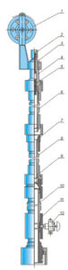
On pump downs and other pressure jobs, the wellhead is equipped with a lubricator (6, 8, and 10) and flow tubes (4) to maintain well control when lowering the wireline tools and cable from atmospheric pressure into the well, which can be at several thousands of pounds of pressure. Bringing the wellbore and the lubricator to the same pressure is known as “equalization.” There have been several cable failures where either the conductor melted or, in more severe cases, the cable parted during the equalization process. The failures have typically occurred one to two feet above the cable head. Wireline subjected to this failure mode will appear burned, and the armor wires may become brittle.
How can this happen? Is it possible for enough heat to be created in the lubricator to melt the conductor and physically change the steel properties, causing cable failure, even with a bottom-hole temperature of less than 400°F? The answer is “yes” if the equalization process is performed too rapidly. Let’s look at how this occurs.
When the lubricator is filled very rapidly, the air inside the lubricator will compress from atmospheric pressure (15 psi) to wellbore pressure (say 3,500 psi) extremely rapidly because there is very little room past the flow tubes for the gas to escape. This rapid compression causes an extreme increase in air temperature because the time frame does not permit significant heat loss. The formula to calculate this “adiabatic” (zero heat loss) temperature rise is as follows:
In practice, you could never compress the air fast enough to keep some heat from being lost, but this calculation sets an upper limit. Using the values above, the calculated temperature of the air after an adiabatic compression would be 1,200°F. If these high temperatures seem unrealistic, consider putting your hand on an air compressor. Even a 150 psi air compressor gets quite hot.
Consider a 26-foot riser with an ID of 5 inches. Inside the riser is a 24-foot tool that is 3.125 inches in diameter. The volume, Vr, filled with air at 15 psia, would be 16,000 cubic inches.
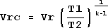
The volume after adiabatic compression, Vrc, according to the formulae to the right, would be only 500 cubic inches.
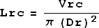
The length of the column of compressed air in the riser, Lrc, is 6 inches.
The calculations above show that the length of compressed air is approximately 6 inches. If the tool is at the bottom of the riser, there would be about 2 feet of cable above the tool and below the grease head.
The 6 inches just below the grease head is where the air would be, and at this point, the temperatures could approach 1,200°F. The insulating material would melt quickly and possibly alter the metallurgy of the steel, causing the wire to become brittle. The rapid gas flow at the same location may result in the severing of the wireline.
What can we do to mitigate the problem?
Although we have spoken of temperature, the real culprit is how much heat energy is available to damage the cable.
The amount of heat available at this high temperature to damage the cable increases directly with the height of the air column and the square of the diameter of the lubricator. In essence, the amount of air retained after compression. Also, remember that the theoretically calculated maximum temperature is based on the condition that the pressure change is so rapid that there is not enough time for the air to escape through the packer and flow tubes or for heat to conduct away by the casing. In the real world, some air will escape, and some heat will conduct away, but if the valve opens fast enough, you can reach temperatures high enough to melt cable insulation and affect the armor metal properties.
In practice, to avoid this problem, consider the following points:
Rapidly filling the lubricator will result in a condition where the air has nowhere to go and thus compresses, resulting in extreme temperatures and high heat energy, which can damage the cable permanently.
The more air in the lubricator can generate more heat.
Filling the lubricator with fluid before equalizing will mitigate much of the air and, therefore, most of the energy to cause damage
Installing a bypass valve just below the flow tubes allows the air to escape much faster.
Loose outer armor wire leads to bird cages, premature cable breaks, and drum crush. There are some general operating practices to reduce the chance of the outer armor wire getting loose, as well as quick and easy field tests to know when the armor is loose. Following these guidelines and knowing when to take the cable to a qualified service center will increase cable life.
Why does the armor get loose?
All cables used in oil field service operations generate torque directly proportional to the load on the cable that is inherent in the design of the cable armor package. The torque of the outer armors is typically two times the opposing torque of the inner armors because, generally, there are more wires on the outer armors, and the distance to the center is larger. When lowered into the well, the tool end of the cable will try to rotate in a direction to unwind the outer armor, which will shift part of the load carried by the outer armor to the inner armor until there is a torque balance in the cable.
As you pull a cable out of the hole, the cable tension increases by the frictional drag on the cable, which is proportional to the speed. The cable will rotate in a direction to further unwind the outer armor in proportion to this increased tension. The greater the speed, the greater the frictional drag, and the more the outer armor will unwind. As you lower the cable back into the hole, the tension reduces, and the cable will try to rotate in the opposite direction to tighten the outer armor again. The faster you lower the tool, the cable has less time to rotate back to a somewhat normal condition.
This combination of fast speeds in and out of the hole will ultimately form loose outer armor and bird cages. Once a bird cage is formed, the inner armor carries the entire load, and the cable-breaking strength is now that of the inner armor only or about 40% of the cable-rated breaking strength.
RULE OF THUMB:
‒ While going in the hole, do not allow the tension at any depth to fall below 2/3 of the static tension at that depth.
‒ Come out at speed no greater than the speed that increases the tension by more than 1 1/3 of static tension at that depth.
In addition to operating speeds, other factors can contribute to the outer armor becoming loose, including:
• Hydraulic pack-offs too tight.
• Flow Tubes do not have enough clearance; recommend minimum tolerance of 4,000 to 6,000.
• Using poly cables in wells with too high a temperature for the plastic sometimes results in excessive embedment of the inner wires into the plastic, resulting in loose outer armor.
As manufactured, the cable’s outer armor wires are pre-formed to a diameter less than its diameter on the cable, so the outer armor wires are tight even at no cable tension. There is no precise tool for measuring “loose armor.” Still, field experience shows that if a small screwdriver blade twisted between outer armor wires can easily move the wires during a time of no tension, it is time to have the cable armor tightened and set with post-forming.
There are several tell-tale signs that a cable is loose, including:
The cable will not lay straight on the ground (torque in the cable).
Mark the cable with paint near the wellhead, and watch the rotation as the cable moves toward the truck. If there is more than one rotation under normal operating tension, the cable may require servicing. When the tension on the cable is released, check the looseness with a small screwdriver, as discussed above.
The top sheave will turn sideways when the tension slacks off, indicating torque in the line.
Sour service alloy lines loosen very quickly. They should be inspected after every job, taken to a service shop, and tightened if required.
What to do when the armor is loose?
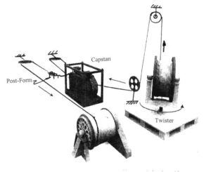
The cable is at high risk when the armor is loose and requires servicing. To tighten the outer armor, the cable service center will set up the cable payoff spool on a rotating platform, as depicted to the right. As you slowly pull the cable off the truck, inspect the degree of looseness of the armor every few feet. As you install the cable back on the drum, rotations of the payoff spool increase as needed along the cable length to tighten the cable. Different parts of the cable may require more turns than others. If adequately monitored, a cable only needs up to 10 turns per 100 feet at the deepest end. Cables that have been neglected or used under severe conditions can require 15-20 or more turns. Under certain conditions following the tightening process, the cable is passed through a series of off-set rollers to set this new condition.
Manage Cookie Consent
F-E-T.com uses cookies to give you the best possible experience on our site. For more information please visit our cookie information page.
Functional cookies
Always active
The technical storage or access is strictly necessary for the legitimate purpose of enabling the use of a specific service explicitly requested by the subscriber or user, or for the sole purpose of carrying out the transmission of a communication over an electronic communications network.
Preferences
The technical storage or access is necessary for the legitimate purpose of storing preferences that are not requested by the subscriber or user.
Statistics
The technical storage or access that is used exclusively for statistical purposes.The technical storage or access that is used exclusively for anonymous statistical purposes. Without a subpoena, voluntary compliance on the part of your Internet Service Provider, or additional records from a third party, information stored or retrieved for this purpose alone cannot usually be used to identify you.
All
The technical storage or access is required to create user profiles to send advertising, or to track the user on a website or across several websites for similar marketing purposes.
 Inner armor coverage refers to how much of the core is covered by the inner armor wires. Traditionally, an acceptable range for inner armor coverage would be 97.5% to 99.5%. Higher coverage results in a stiff cable and lower coverage results in problems with plastic prematurely exuding through the inner armor wire (right photo), resulting in loose armor or, in extreme cases, premature electrical failure.
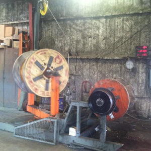
 On pump downs and other pressure jobs, the wellhead is equipped with a lubricator (6, 8, and 10) and flow tubes (4) to maintain well control when lowering the wireline tools and cable from atmospheric pressure into the well, which can be at several thousands of pounds of pressure. Bringing the wellbore and the lubricator to the same pressure is known as “equalization.” There have been several cable failures where either the conductor melted or, in more severe cases, the cable parted during the equalization process. The failures have typically occurred one to two feet above the cable head. Wireline subjected to this failure mode will appear burned, and the armor wires may become brittle.
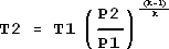
 All cables used in oil field service operations generate torque directly proportional to the load on the cable that is inherent in the design of the cable armor package. The torque of the outer armors is typically two times the opposing torque of the inner armors because, generally, there are more wires on the outer armors, and the distance to the center is larger. When lowered into the well, the tool end of the cable will try to rotate in a direction to unwind the outer armor, which will shift part of the load carried by the outer armor to the inner armor until there is a torque balance in the cable.